VHF Crystal Oscillators
Written by Charles Wenzel
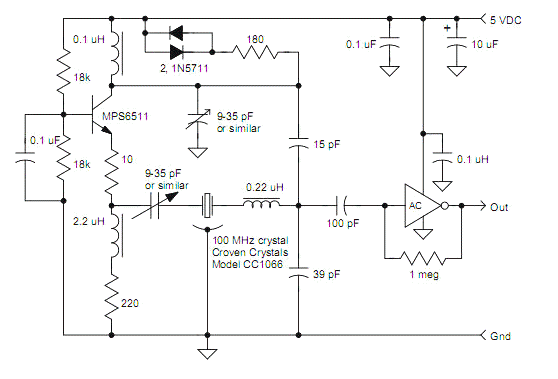
VHF crystal oscillators typically employ 3rd or 5th overtone crystals for superior stability and jitter performance. Since the crystal will readily oscillate at the fundamental or lower odd overtones, some method of selecting the desired mode is needed. The following circuit uses a simple grounded-base configuration with a tuned circuit in the collector to select the desired mode and to provide feedback for oscillation. The 0.1 uH resonates with the trimmer capacitor and the series combination of the 15 pF and 39 pF at the desired frequency, 100 MHz in this case. The 15 pF and 39 pF divide the collector voltage and step the current up sufficiently to reliably start oscillation. Oscillation builds until the 1N5711 diodes begin to conduct, loading the collector sufficiently to limit the oscillation level. This type of limiting keeps the transistor in a linear region. The lower voltage across the 39 pF is sufficient to drive a self-biased AC logic inverter.


The circuit loads the crystal with about 15 pF but the crystal used in the prototype was designed for series resonance. The 0.22 uH in series with the crystal easily brings the frequency down and the value may be varied to move the tuning window up or down. The choke could be eliminated by specifying the CC1066 to tune with a 15 pF load. In the event the frequency window needs to be raised, the inductor could be replaced with a capacitor. The tuning range of the 9-35 pF trimmer will be greater with series inductance, however. The range of the prototype is +- 18 ppm with the 0.22 uH, +-12 ppm with a jumper, and only +-9 ppm with a series 22 pF. By selecting a series-resonant crystal and choosing an inductor to add in series to bring the frequency back down, a wider tuning range results, giving the circuit more tolerance to component variation.
The trimmers could be eliminated for application not requiring precise frequency. The collector inductor should be a precision type and the collector trimmer would be replaced with a combination of two fixed capacitors selected to peak the oscillation. The precise value will be a function of the board layout and transistor type, and using two capacitors makes it easier to hit a precise value. The crystal trimmer and 0.22 uH inductor could be replaced with jumpers if the crystal is specified for a load near 40 pF. The crystal could be specified for a load capacitance of 22 pF and a fixed capacitor could be added in series, selected to bring the frequency close to the desired nominal value. That fixed value will be near 47 pF, somewhat dependent on the layout and component choices.
The circuit is fairly forgiving to component variation. The transistor isn’t critical; even the relatively slow 2N4401 worked well in the prototype. The 180 ohm in series with the diodes may be increased for higher drive level and a larger signal at the input of the AC gate. Other fast logic types with high input impedance like UHS Tiny Logic may also be used. The 2.2 uH may be replaced with a jumper with minimal loss in performance. For the best noise floor, leave it in and increase the 180 ohm to 470 ohm to drive the logic with faster edges. AC logic has robust input protection diodes but other logic families do not, so make sure to not set the amplitude too high. The floor will vary from -140 to -150 dBc at the output of the gate as a function of the oscillation level. The noise at the input of the gate is about -152 dBc, improving to about -158 dBc with a quality low noise RF transistor and higher signal levels. That voltage may be buffered with a high speed op-amp for sine wave output.

