Croven Crystals Model CC1066
Written by Charles Wenzel
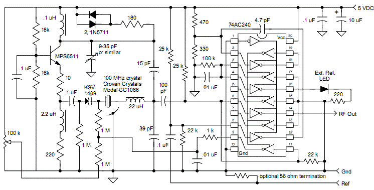
The Croven Crystals Model CC1066 makes an excellent low jitter clock for a variety of instrument applications. For those applications where synchronization with an external reference is desired (“external reference input”), a single 74AC240 line transceiver may be employed. The circuit below uses the VHF oscillator previously described to drive two gates within the ‘AC240. One gate simply buffers the signal and provides a high current logic output in a similar manner to the earlier application note. The other gate is used to sample the RF. The reference input signal is converted to a short pulse that is applied to the tri-state control of the sampling gate, causing that gate to pass a short sample of the oscillator’s output, then switch to a high impedance state. Since the sampling gate switches to a high-Z state when it is not sampling, the sample pulses may be relatively far apart without significant droop in the sampled voltage.


As a result, the sampled “beat note” is large even when the reference frequency is a relatively low frequency. The only requirement is that the reference frequency be an integer sub-multiple of the VHF crystal oscillator’s frequency. For example, a 5 MHz external reference will generate sample pulses every 200 nS. But the pulse is short enough to sample a 100 MHz waveform and produce a large output at pin 9. In this implementation, the output of this sampling phase detector is simply low-pass filtered and applied to a varactor diode, forming a first-order PLL. The gates are biased such that the sampling gate switches to a high-Z state when no reference is present. This high-Z state allows the frequency of the VHF oscillator to be controlled by the 100k potentiometer, allowing the system to revert to the mechanical tuning. The tri-state pulses are also used to “sample” ground, causing a low level output to drive a “No External Reference” LED. Connect the anode of the LED to +5 and the 220 ohm to pin 16 to have the LED light when the reference is present. Another option is to connect the resistor to pin 16 and connect a dual-colored LED to +5 and ground such that the color changes from red to green when a reference is connected.
Since the reference input is converted to very short sample pulses, just about any reference frequency expressed as Fosc/N for values of N up to about 20 may be used. A prototype readily locked to a 5 MHz reference (100 MHz / 20) and a 5.8823529… MHz (100 MHz / 17), for example. Typically, the reference frequency would be 5 or 10 MHz. For values of N above 20, it may be necessary to increase the value of the 1 megohm from the frequency adjust potentiometer so that the more widely spaced sample pulses can take control of the tuning line.

